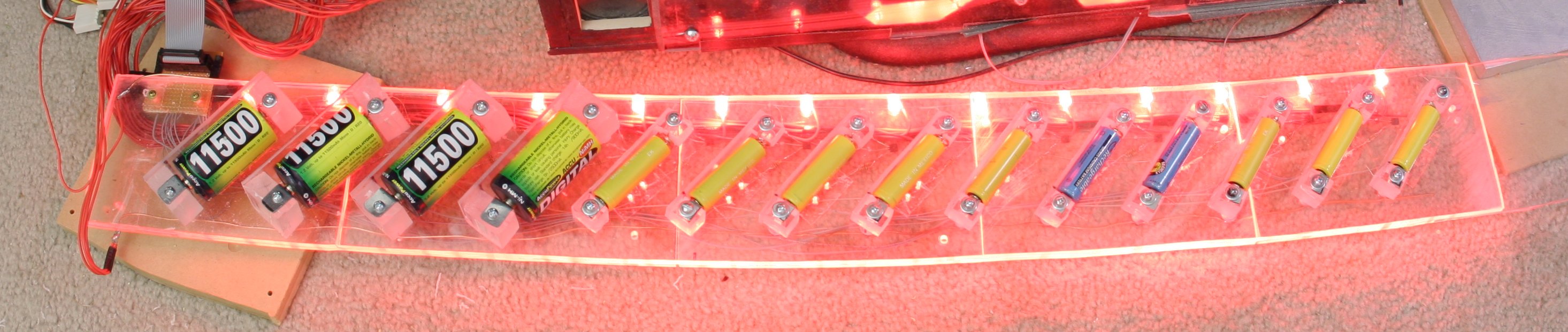
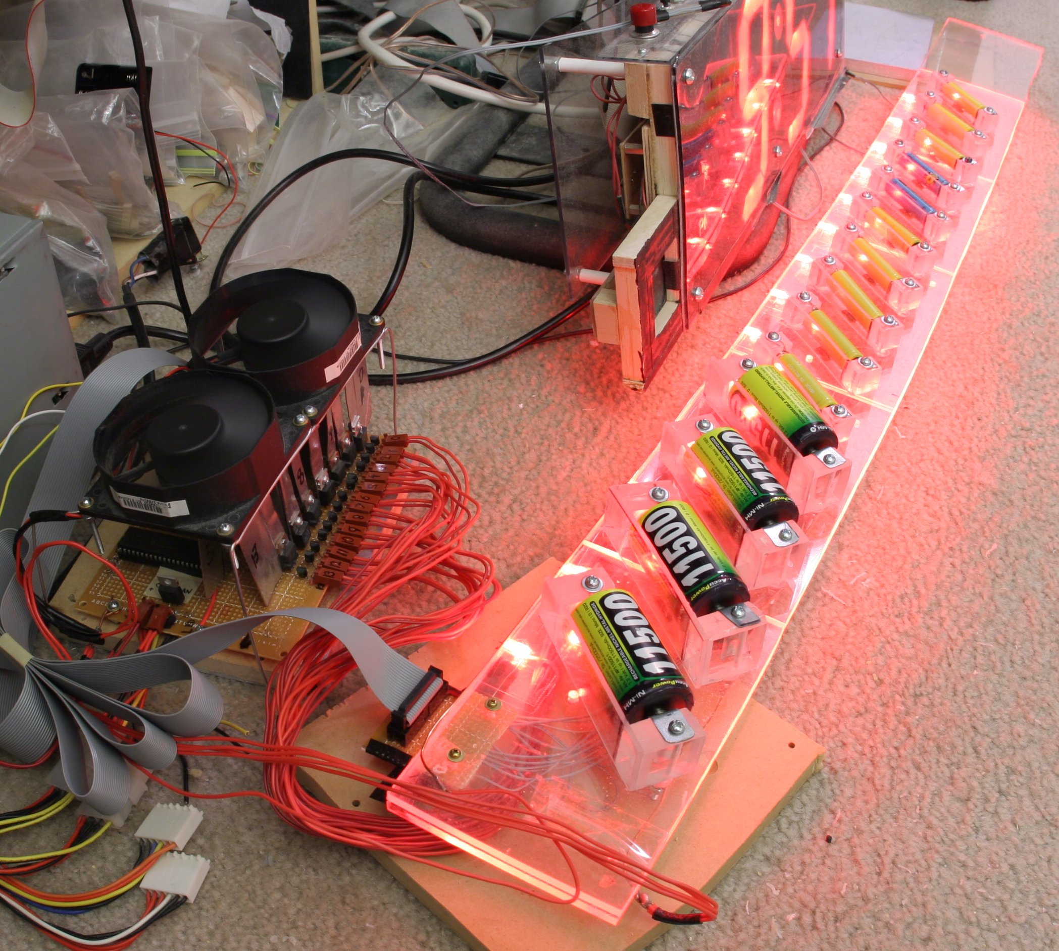
It's the ultimate battery charger. 14 batteries on separate circuits.
The AA's get constant 1A and the D's get constant 2A for a compromise
between fast charging and cost. With batteries charged on separate
circuits, there is no memory effect.
It's powered by a dual microprocessor board. Next time, use a 50
conductor ribbon cable for the high current leads. A 25 conductor
ribbon cable was added later on for the temperature sensors.
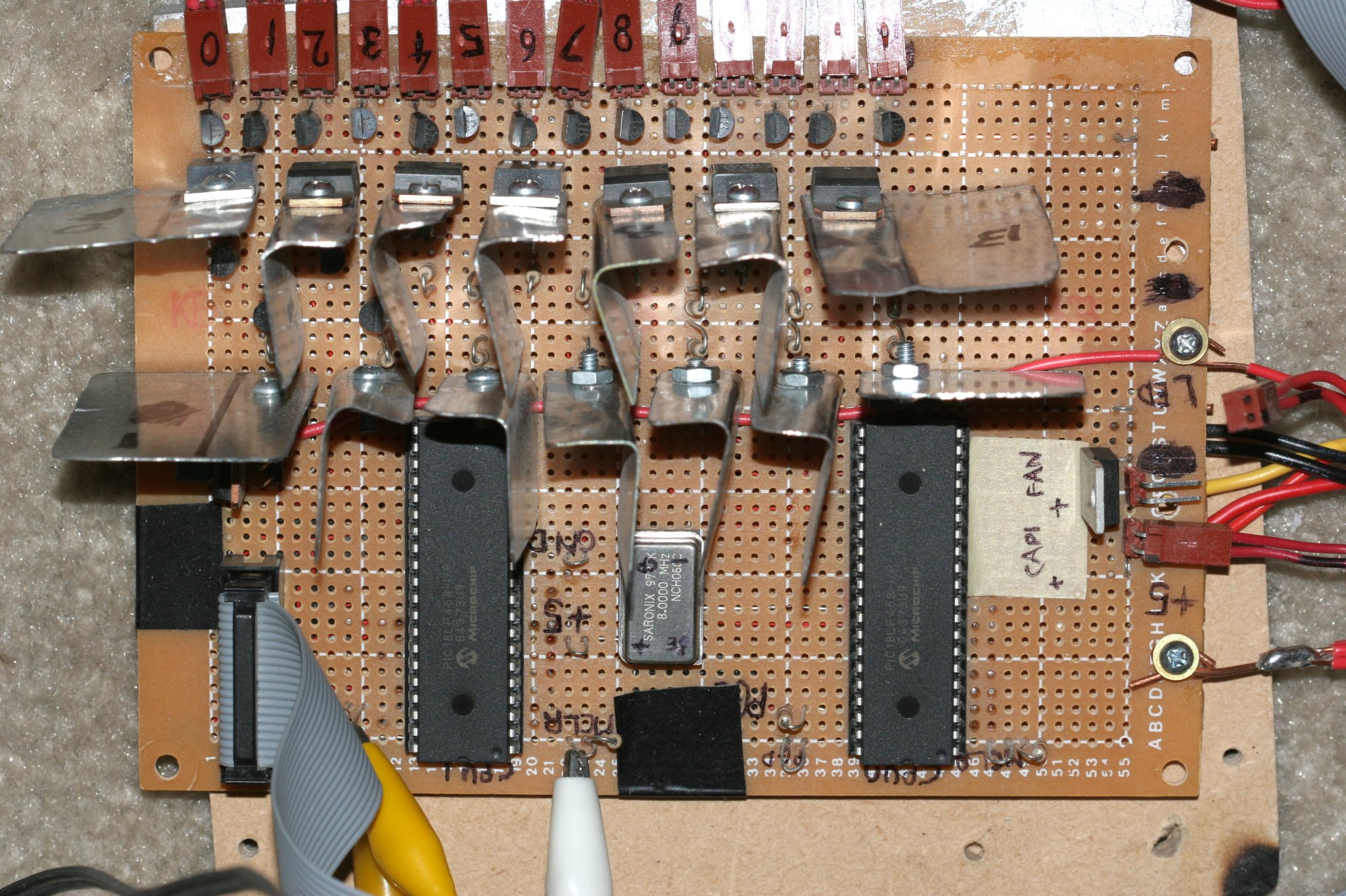
That's right. Dual PIC18LF458 microprocessors because it was the most
practical way of getting 14 analog inputs. This battery charger has
more computing power than a Vic 20.
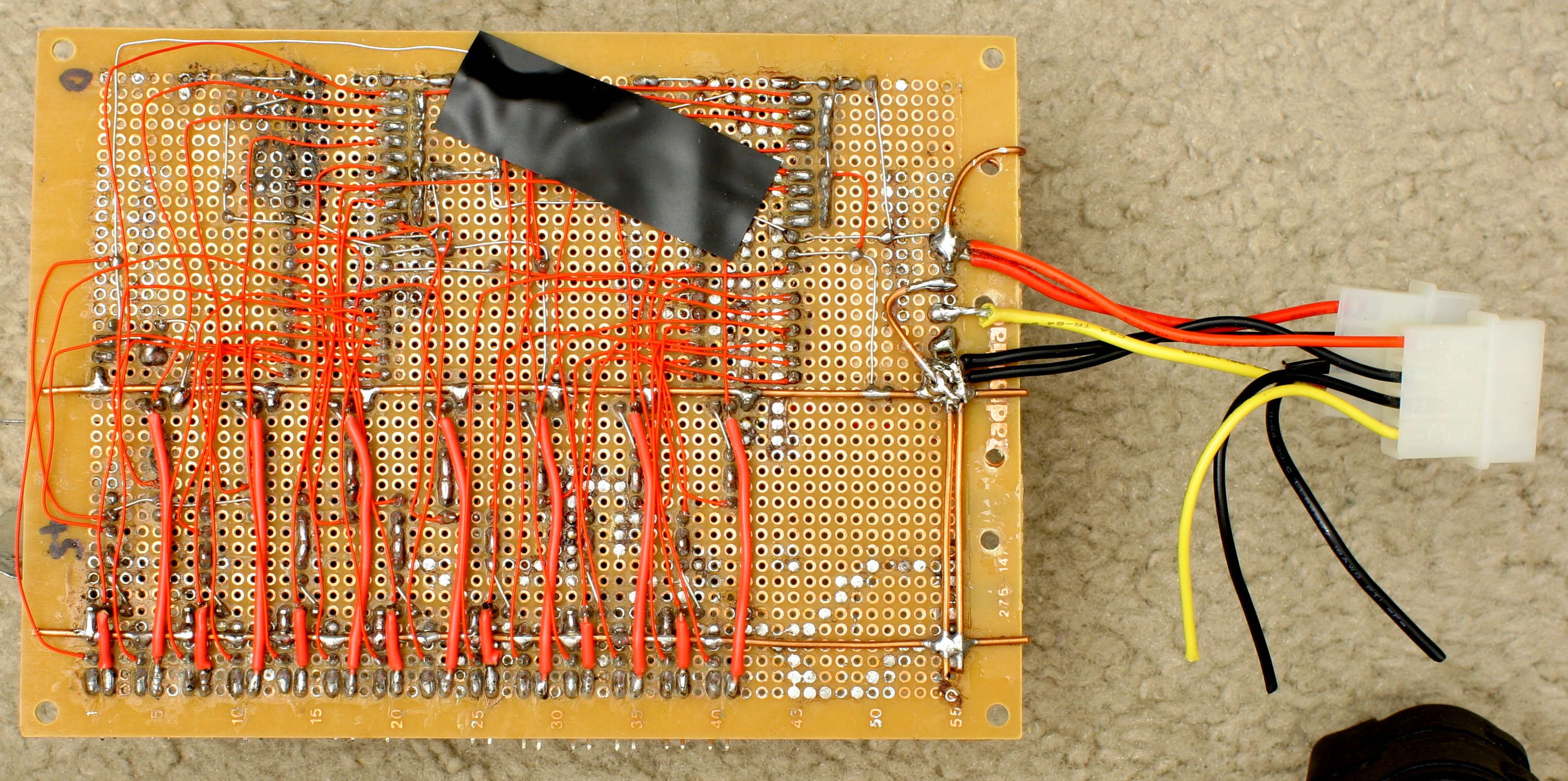
Point to point soldering involving some very high current copper
busses. That was a true mark of senility because it had to be rebuilt
some 3 times before it actually worked. Next time, make the
transistors form a nicely spaced out ring around the microprocessors
instead of cramming them together.
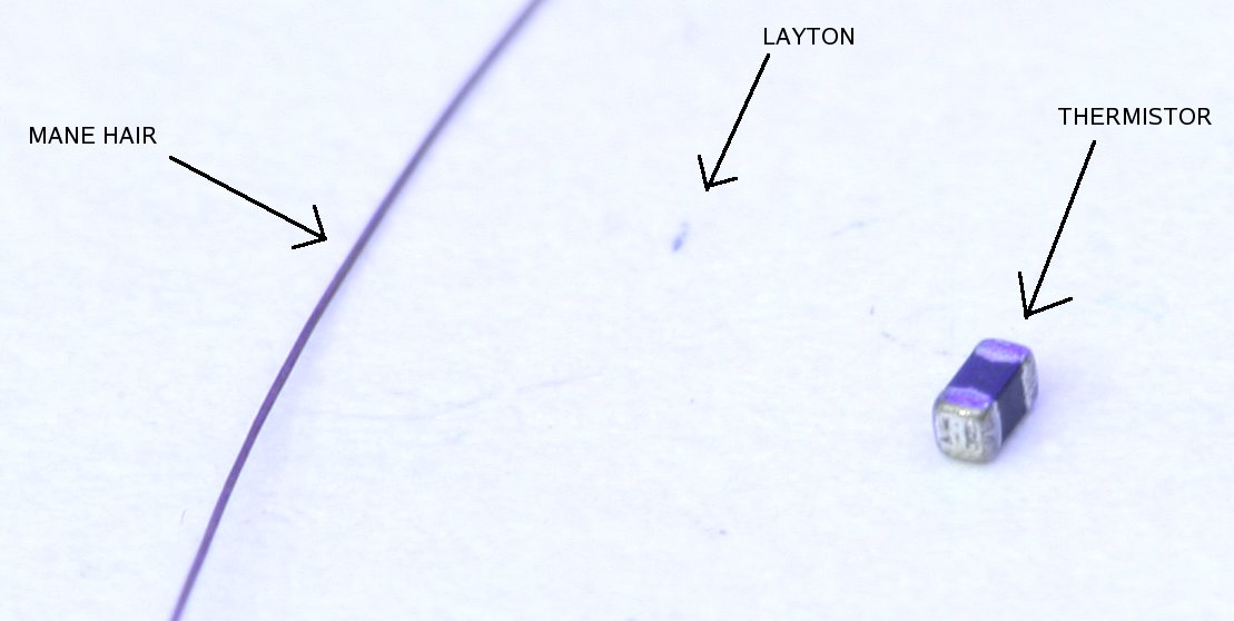
Unlike any commercial charger, SheCharger uses temperature to regulate
charging. This is the most efficient way to regulate charging of
NiCad/NiMH batteries but it's expensive. It took extremely
miniaturized thermistors to get the cost down.
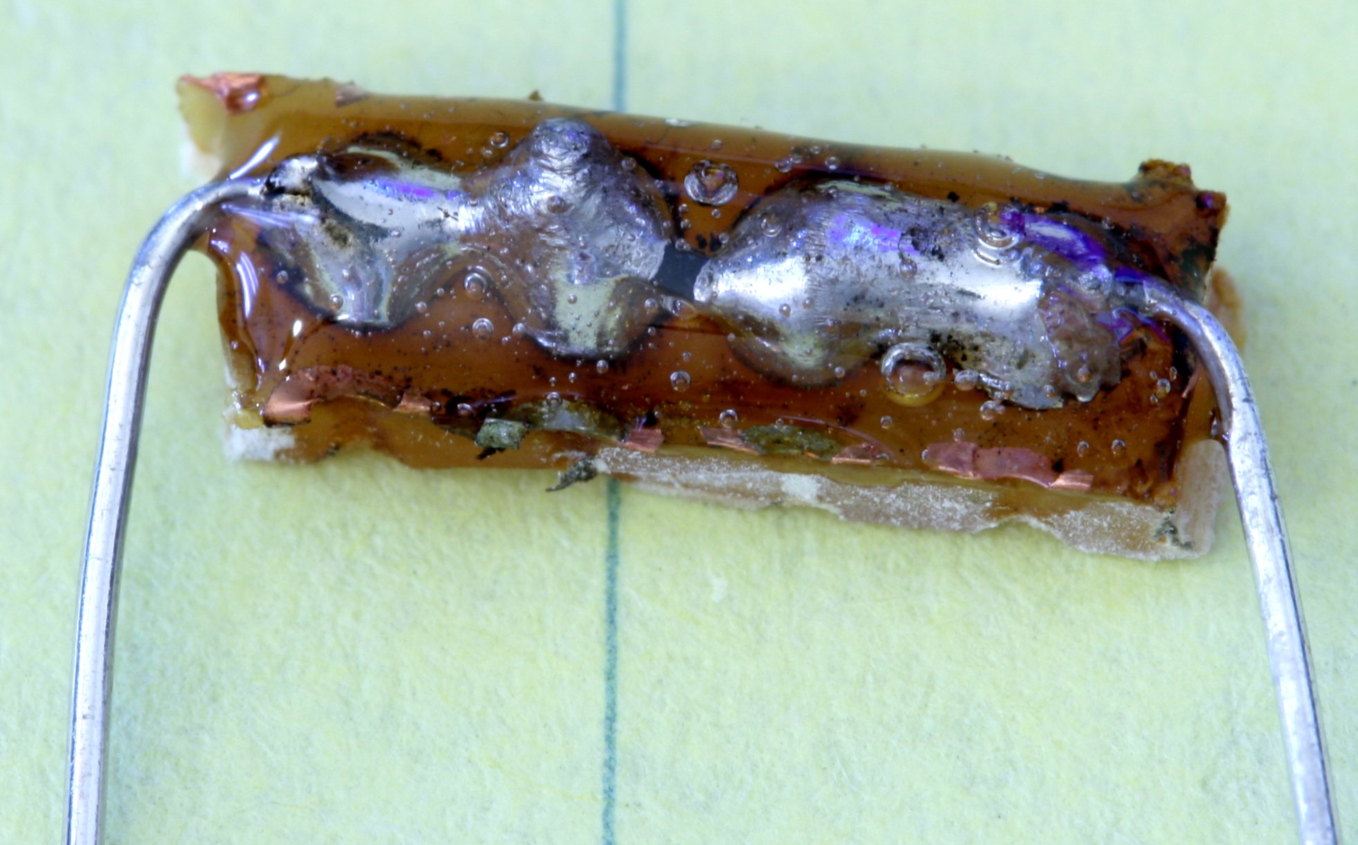
The tiny thermistor wouldn't survive impacting by a battery, so it had
to be soldered into a custom package. Mainly it was soldered between 2
pads on a copper plated protoboard and encased in epoxy. Don't be
suprised if you burn up a dozen thermistors trying to get this
right.
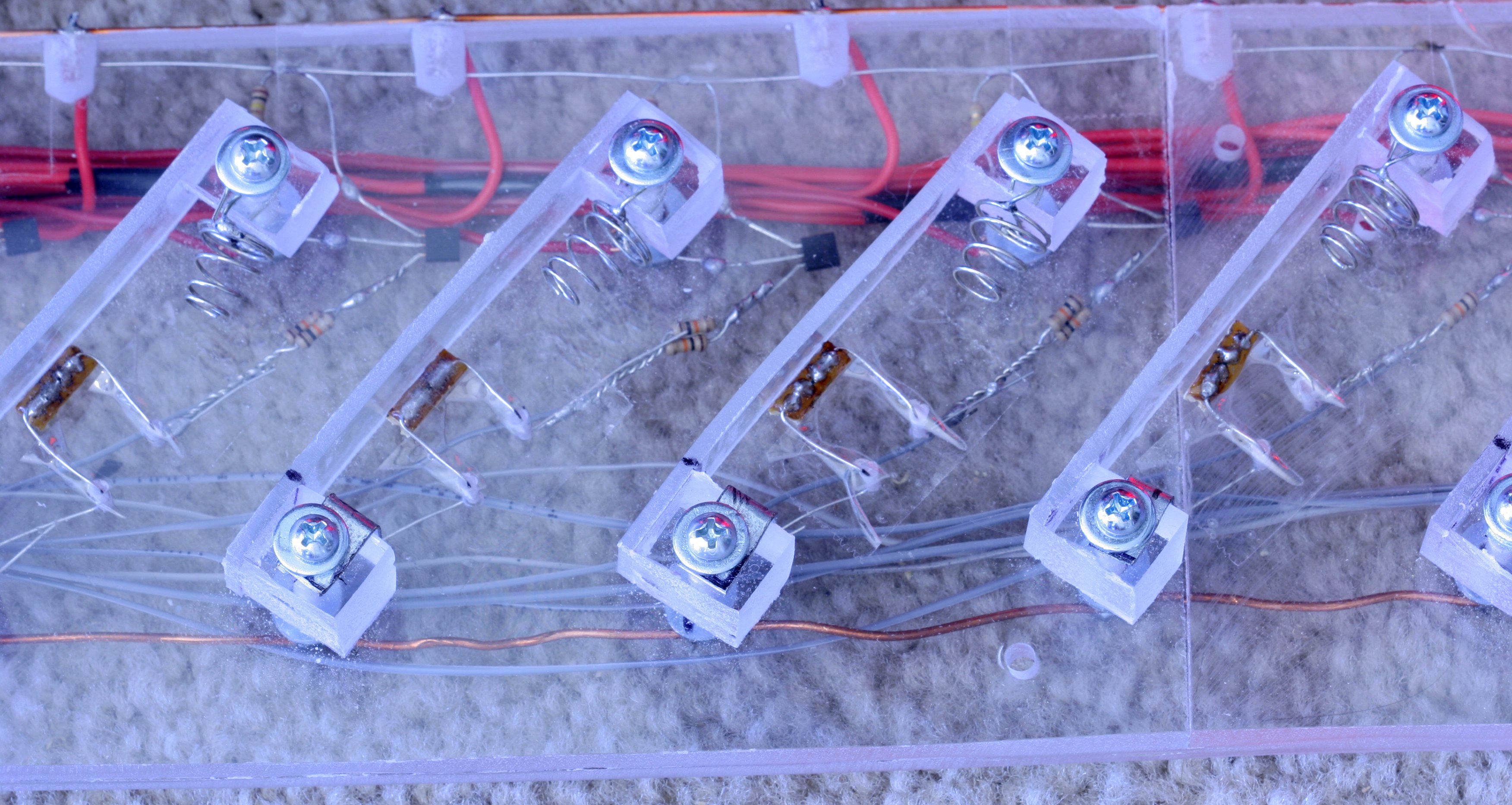
The thermistors were secured in the battery holders.
Inventing a battery clip which looked cool took some doing. These were
made from grinding up 4AA battery holders and soldering the springs.
Small pieces of sheet metal were ground up for the + terminals. There
was no other reason for going through that.
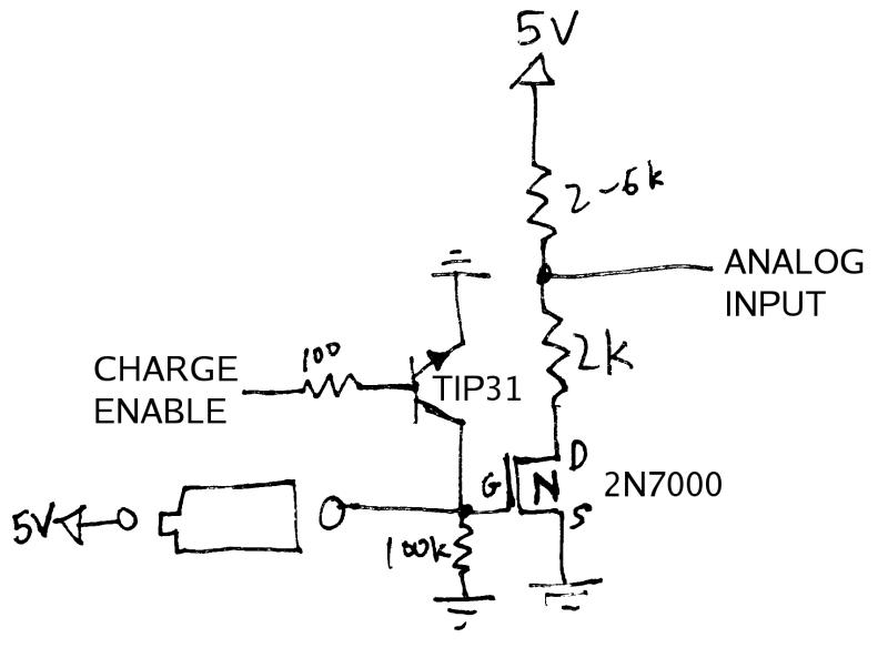
The cheapest method was to base each charging circuit on a power
transistor. The power transistor provides a ground to the battery with
constant current but the hard part was detecting when a battery was
inserted. Turns out, without a battery, the transistor's collector can
be pulled down to 0V by a big resistor. When the battery is inserted,
the transistor's collector goes to at least 3V.
That's just enough to turn on an N-type MOSFET. With the MOSFET turned
on, the grounding is enabled for a thermistor and the thermistor reads
a valid temperature. With the MOSFET turned off, the thermistor has no
ground and reads 5V, thus battery insertion and temperature are
multiplexed onto 1 pin.
The 2N7000 MOSFET seems to have a high failure rate in this circuit
because there is no ground. May have to upgrade to some power
MOSFETS.
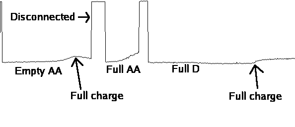
The actual data received by the microprocessor shows when the battery
is disconnected, when it's being charged, and when it's full.
Once the temperature spikes, charging switches to a trickle charge.


(C) 1997-2024 Starving, flat broke, usually unemployed Programmers
Hosted all these years by Sourceforge